Here we discuss how we went about designing and building the SpinWheel.
The Idea
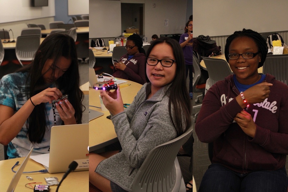
The idea for a stylish wearable device to encourage the pursuit of science and engineering originated in 2017 with one of our regular outreach events on Yale’s campus. We invited high schoolers to campus to use breadboards, LED strips, and a motion sensor to create a motion-sensing bracelet.
The feedback after the event was overwhelmingly positive and confirmed our conviction that building something beautiful can overcome initial fears about math and science. We were particularly encouraged when students professed their surprise that math and engineering could be so beautiful and a commitment to exploring these concepts further.
“Before, I had never really worked with electronics but now I am definitely going to start messing with it more.”
“I am excited to learn to read the codes and be able to change things for the lights. I will try to explore Arduino in the future.”
Building on this idea, we have developed the SpinWheel. Through motion sensors and programming capabilities, it provides a rich platform for teaching physics and computer science. Potential lesson plans include vectors and kinematics, physics of light and color mixing, intro to programming, and even signal processing. The hands-on “adventures” that come with the device build on these lessons and bring together science and art.
(A similar desire, to present math as beautiful and creative subject, was behind the later creation of our Fractals and Art lesson plan, but we digress…)
Turning it into a self-contained device
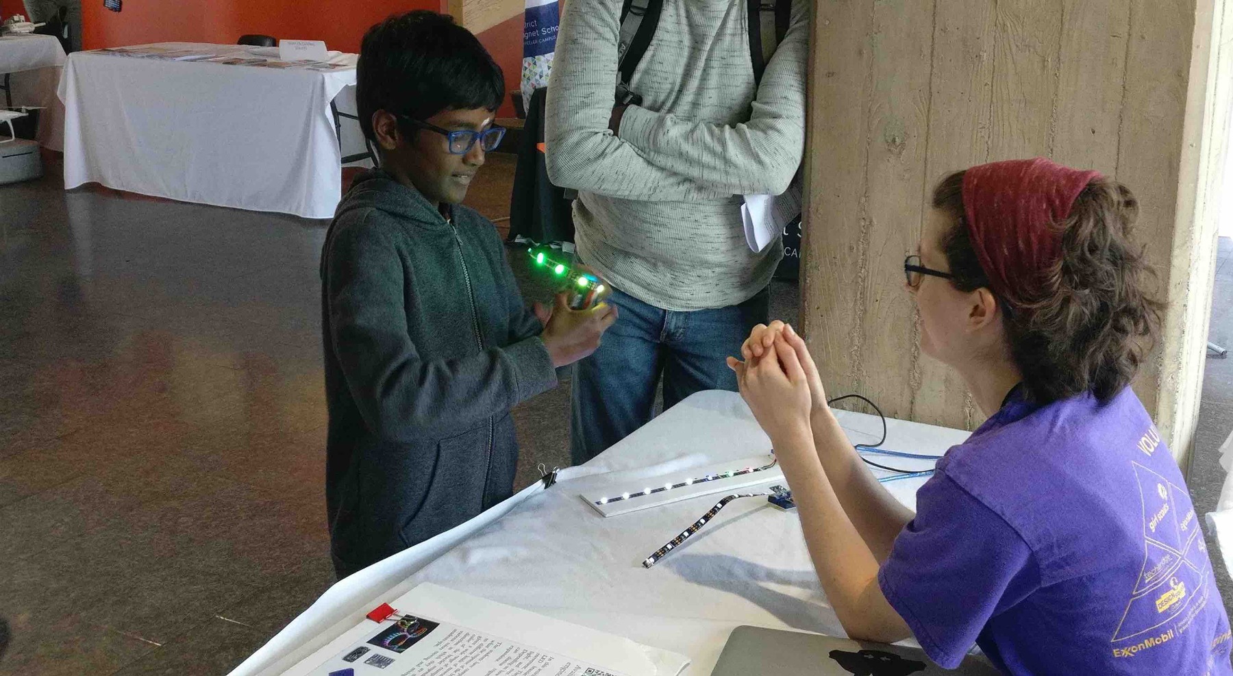
We continue to use the LED-strip bracelet as a platform to teach electronics; however, this activity requires experienced volunteers to help with debugging and wiring. With the SpinWheel, we desired to create something self-contained: a beautiful wearable device that the student can confidently use to explore the marvels of science on their own. This led us to our current design, which is both more resilient and quite a bit more elegant than the initial LED-strip bracelet.
In the rest of this page, we will further describe the design process and our choice of tools.
In an advanced section of the “The SpinWheel Field Guide”, we will discuss the design and testing process in more detail, in the hope that young makers will feel empowered enough to create their own devices. In particular, we would like to demystify what can be the most terrifying part of the process: debugging an initially failing new design.

Initial parameters, component selection, and rough shape
Since accessibility was our top priority, we decided to base our device on the wonderful, open source Arduino platform. This platform has been extensively tested by the world-wide maker community and features a simple installation procedure. For the main controller on the board, we chose the Atmega32u4 chip, which is directly supported by the Arduino software. This particular chip has a built-in USB interface that the students can use for programming. The open hardware community, and in particular the Arduino organization, has used this chip in many designs, providing a wealth of documentation that made our work much easier.
Moreover, our desire to use the minimal amount of extra components led us to choose the Atmega32u4 chip, as this particular chip has a built-in USB interface that the students can use for programming. This same chip is used in the popular Arduino Leonardo and Arduino Micro boards. The open hardware community, and in particular the Arduino organization, have used this chip in many designs, providing a wealth of documentation and reference circuit diagrams that made our work much easier.
In addition to the microcontroller, we picked a 9-degrees-of-freedom motion sensor (for acceleration, rotation, and magnetic field sensing), a LiPo battery charger, and the required support components.
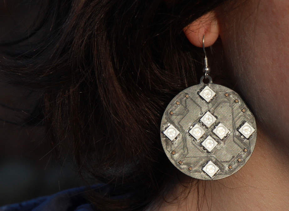
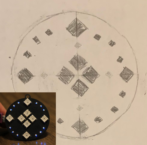
We simultaneously iterated through the physical parameters for the device to arrive at something that was wearable, beautiful, and included sufficient LEDs to represent cardinal directions, measured tilt, and other physical quantities.
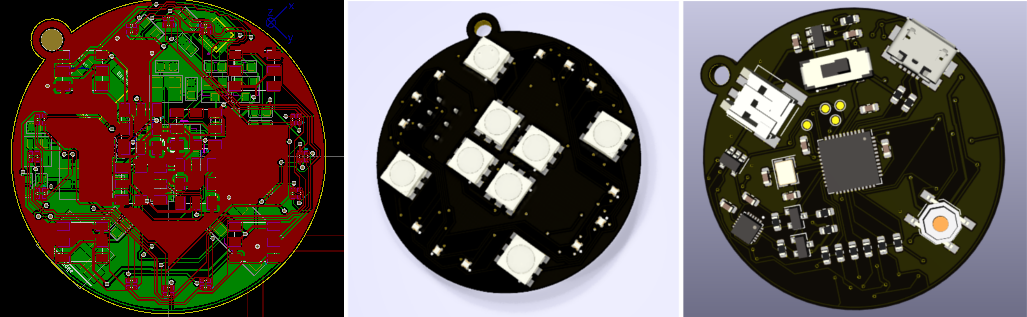
Creating the circuit diagrams and the board layouts
Once we had our components and a rough sketch of the layout, we began designing the circuit board using computer aided design (CAD) tools. In a typical electronic design software, one starts by drawing the abstract circuit diagrams. In our case, this mostly mostly involved copying the reference schematics provided by the manufacturers of the microcontroller, motion sensor, and battery charger. The main challenge was fitting all of the components into a compact form factor and completing the circuit without crossing electrical components.
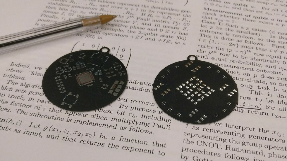
Testing the newly printed boards
Before we were comfortable pushing the project forward, we wanted to test the SpinWheel design under various conditions. For that purpose we ordered multiple unpopulated breadboards, on which to build and test the prototype device.
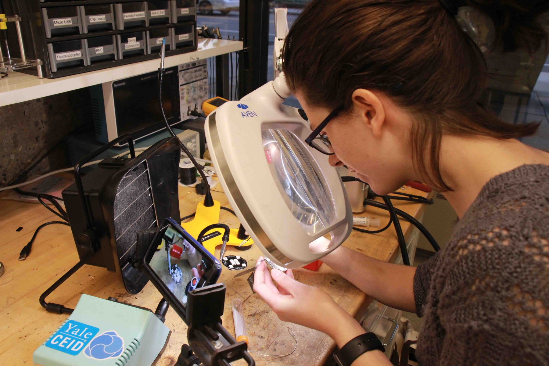
Given its small components, the SpinWheel is best assembled by robots. However, the cost of production is prohibitively high unless boards are ordered in bulk. Therefore, we decided to assemble a small number of test boards by hand before sending the SpinWheel off to our robotic colleagues. This permitted us to double check the performance of each component (and indeed led us to change some of our initial design choices), thus ensuring that the final device will work reliably.
More about the software
The SpinWheel is suitable for a very rich Computer Science curriculum, covering many difficulty levels and topics as outlined above. However, our main focus was to have easy on-boarding for students who have never programmed before. Therefore, we are structuring the libraries so that a very small amount of code is sufficient to create interesting patterns and responses from the device. Advanced users will also have the option to use a lower-level set of operations to create even more imaginative patterns.
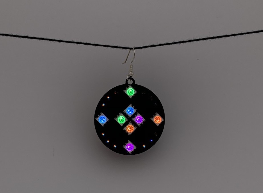
Final results
This is the SpinWheel: a brilliant, easily-programmable, wearable device through which students can explore computer science and physics while creating a beautiful accessory for themselves.: