Creating the blueprints for an electronic device like the SpinWheel involves two parallel processes. On one hand, one needs to ensure the electronic circuit is functional in the abstract. On the other hand, this abstract circuit needs to be laid out on a two dimensional circuit board without crossing wires, and in our case, without placing components in unseemly locations. Here we describe this process, starting from simple child-friendly tools, and slowly evolving it until it is sophisticated enough to produce a hobby device like the SpinWheel.
Functional Prototypes: Electronics vs Mechanics
In the early stages of a project it is important to compartmentalize the often conflicting goals of a design. On one hand, there would be certain technical requirement for the project, like the capability to sense motion or to turn on an LED. On the other hand, the physical and mechanical properties of the device to be built might have certain constraints, whether for practical reasons (e.g., mounting requirements for a sensor, weight requirements for a drone) or aesthetic reasons (e.g., creating a beautiful STEM educational kit). It helps to address these separately at the beginning. A kind of a divide and conquer strategy.
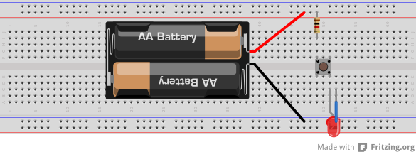
One prototype can be made where only the electronics are tested: do not worry about the placement of components or the size of the final circuit board, rather just ensure that you can test that the components work together in principle. A convenient way to do that is to buy “breakout boards”, i.e. small boards on which the desired components are already mounted for easy testing. For instance, our control chip and our LED chips were rather small and very difficult to connect on their own. Before designing the SpinWheel board we wanted to test them, so we bought a small “development board” that uses the same control chip, and we also bought an off-the-shelf strip of LEDs (the same ones we wanted to use in our custom design). This permitted us to test that the different components were indeed compatible, before committing to them.
This first prototype, which serves to simply test the electronic logic behind the SpinWheel is called the electronic functional prototype. “Functional” because it only tests the electronic functions of the future device, without concerning itself with any mechanic or aesthetic constraints.
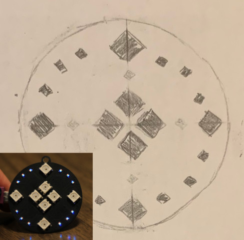
Similarly to creating the functional prototype, we would want to create design prototypes of varying sophistication. Maybe a simple sketch is enough, or maybe we would mold a mock device out of polymer clay. The choice depends on how important the look of the device would be for us. In the case of the SpinWheel it is quite central.
Circuit Diagram vs Layout
While constructing the functional prototype we probably made various diagrams as guides to ourselves. Given that the functional prototype was not concerned with form and aesthetics, rather only with logic and proper connections, our diagrams would also be only a guide to which wires to connect together. This type of abstract diagram is called a circuit diagram and it does not tell us how to physically arrange the components on the final board.
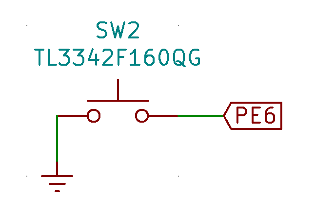
SWitch2. That button is connected by a green “wire” on the right to a label representing one of the many pins of the controller chip: the one that will be detecting whether the button is pressed. Towards the bottom we see that the button is connected to the ground (or earth) of the circuit.
The symbols used in such a diagram do not necessarily look much like the physical components they represent:
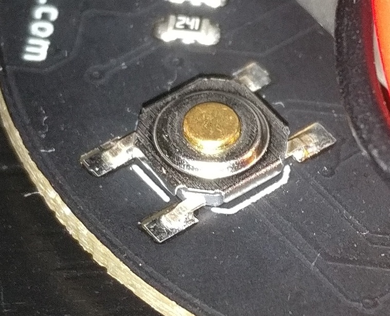
SWitch2 actually looks like: A button connected to the board by the four small soldered legs.
To bridge the gap between the circuit diagram and the actual physical realization of that diagram one typically uses a Computer Aided Design (CAD) tool. Such a piece of software lets you translate the diagram into a detailed physical layout for your board and components, as opposed to the messy jumble of reusable breakout boards that was the functional prototype.
CAD tools store libraries of parts. Each part has a diagram symbol to be used when preparing the circuit diagram and layout footprint connected to that symbol, which represents the physical appearance of the part (in particular, it knows what pads need to be placed on the board in order to solder the part on).
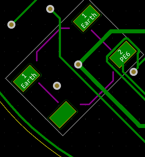
One uses the CAD tool to move the footprints around until a satisfactory placement is achieved. The CAD tool also keeps track (thanks to the circuit diagram) of which pads of which footprints have to be connected by traces. This last task, of placing the traces could either be extremely frustrating or seen as a fun puzzle, as it is quite difficult to connect all components without crossing paths.
Do it yourself
A good place to start, even for complete novices, is with hobbyist tools like Fritzing and Tinkercad which provide a rich and friendly graphical interface in which to experiment with simple circuits, make diagrams, and even board layouts. The jump to more professional tools like Upverter (an online CAD tool with a reasonable learning curve) and KiCad (the tool we used for the SpinWheel) can be very intimidating, but by starting with simpler projects it can be achieved even with selfstudy and no external help.
We would definitely suggest playing with only functional prototypes and breadboards for a while, to build confidence, before jumping into working with CAD tools. When making your own circuit boards, we would also suggest starting with through-hole components, as they are much easier to solder for novices than other options. And certainly do not hesitate to get inspiration from other designs when working on your own. For instance, we consulted the opensource designs by Arduino, SparkFun, and Adafruit extensively while designing the SpinWheel. If you would like to download the KiCad files for the SpinWheel, you can find them at our git repo.
